Installation Instructions ADA the Commercial Sensor Faucets
Motion Sensor Faucets Installation Instructions
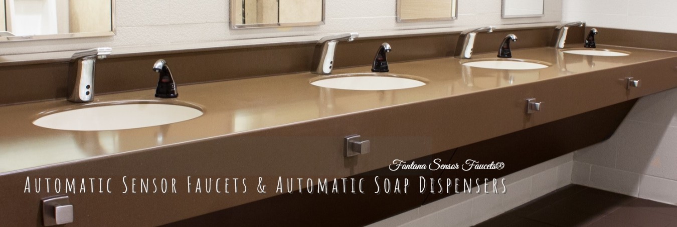
The Hands Free Motion Sensor-operated mounted faucet, is made of solid brass construction body faucet anti-erosion, anti-abrasion and high strength. They come in different finishes chrome, oil rubbed bronze, or gold plated finish. These Sensor Faucets are ADA compliance and fit for residential or commercial use. A/C and Battery Powered Faucet Fontana Sensor Faucets
Prior to installation
Before installing the sensor faucet, please open the box to check the packing list whether it includes all the items as the above.
Installing Sensor Faucet
Please install touchless sink faucet per installation instruction. Note: We dont supply inlet pipe. Before installing Control module assembly, please check your inlet pipe whether it could be connected to the deck enough.
Please shut off the water valve of inlet pipe before installation.
Please check whether detection zone factory set as SPECIFICATION meets your requirements; otherwise please adjust it complying with your requirement. The steps as follows:
Adjustment of sensor distance
: Loosen the 600MM flex hose deasil from faucet assembly. Loosen two nuts under the base gasket using head screwdriver, please push the sensor eye slightly and take it out. Loosen six nuts from the control module assembly, open and take out battery compartment, put 4AA alkaline batteries into battery compartment. Connect fiber optic cable battery compartment. (Note: When connect optic cable to battery, without sensor object near the sensor location) Please use your hand to approach the sensor eye slowly from exceeding 30cm, When your hand in sensor location, you will hear beep from the battery compartment, meanwhile, the LED in the sensor eye flash red. A small nut is on the chipset located on the basis of sensor eye, turn around the small nut anti-clockwise to long or short of sensor distance. When finished adjustment, please take off fiber optic cable from battery compartment, meanwhile take out the batteries. Put the sensor eye into faucet assembly, put the faucet assembly together with fiber optic cable through the holes into the base of trim plate without border & base gasket, and then screw the two nuts of gasket.
Connect flex hose to basis of spout
(direction towards without nut).
Screw the two studs into trim plate with head screwdriver.
Put two (2) fender washers on the holes on top of deck which for inserting two studs. 5. Insert faucet assembly and fiber optic cable together with flex hose and studs through holes in deck. 6. Using two (2) fender washers into the two studs from below deck, and then put two (2) finger nuts supplied into two studs, screw them into studs from below deck to secure trim plate on deck.
Install Control module assembly
Before install Control module assembly, please check the place of deck and installation place of Control module assembly. If confirmed, please put the Control module assembly onto the wall first, and use drill bit to anchor the four holes. (Figure 4 Control module assembly) 1. Using ø6mm drill bit follow the four anchors to drill four holes into wall. 2. Using hammer knock the four plastic wall anchors supplied into wall. 3. Installing Control module assembly to wall, knock four selftapping screws into four plastic wall anchors. Then the Control module assembly is installed onto wall.
Connect flex hose to solenoid valve
Use wrench to connect the free end of the flex hose to the outlet side of the solenoid valve.
Connect fiber optic cable
(Figure Connect Fiber Optic Cable) 1. Connect the free end of fiber optic cable to the Control module assembly. 2. Thread the connector cap with nut onto the Control module assembly to secure the connection. Note: Please keep the sensor plastic cable clean and dry when install it, in order to keep the machine workable. Note: When installation is finished, please use a small piece of soft and dry cloth to wipe away the sensor eye slightly.
Battery installation
Note: DO NOT INSTALL THE BATTERIES UNTIL THE FAUCET IS COMPLETELY INSTALLED. If the batteries are installed before the fiber optic cable has been connected to the Control module assembly, the faucet will not properly set the sensing range for the sink on which it has been installed. Loosen the cap of control module assembly with head screwdriver, and loosen the cap of battery compartment. To ensure proper operation, inset four (4) new C-size alkaline batteries. Check that the orientation of each battery matches the positive (+) and negative (-) symbols shown in the bottom of the battery compartment. Make sure that spout is properly centered and that no objects are in the sink. Close the cap of battery compartment and cap of the control module assembly follow the above steps.
Connect inlet pipe
Please connect inlet pipe to control module assembly. Note: Please use the proper inlet pipe into diameter of inlet on solenoid valve. Very Important: Please turn off the inlet pipe valve to install the inlet pipe.
Turn on the inlet pipe valve
Please turn on the inlet pipe valve, to check whether water flowing and sensor distance meets your requirements. If not, Please follow the above ways to adjust the sensor distance again. BATTERY REPLACEMENT PROCEDURE Battery powered faucet with 4AA alkaline batteries can be used for 2 years at 200 cycles a day. When the batteries are low and need to be replaced, the faucet will signal you, when your hand approach the sensor location, the LED will flash red three times quickly without water out; when without object to approach the sensor location, the LED will red one time per four second. At this point we recommend battery replacement. To replace batteries: Note:Water supply to the faucet does not need to be turned off when replacing batteries. Loosen the cap of control module assembly with head screwdriver, and loosen the cap of battery compartment. To ensure proper operation, inset four (4) new C-size alkaline batteries. Check that the orientation of each battery matches the positive (+) and negative (-) symbols shown in the bottom of the battery compartment. Make sure that spout is properly centered and that no objects are in the sink. Close the cap of battery compartment and cap of the control module assembly follow the above steps. Upon installation of the batteries, faucet will begin a new self calibration procedure. SOLENOID SCREEN FILTER CLEANING PROCEDURE Before cleaning the screen filter, turn off the water supply at the supply stop(s). Turn off the inlet pipe. Activate the faucet to relieve any pressure in the system. Clean the screen filter using fresh tap water. If necessary, use a small brush to clean. Use caution while cleaning to prevent damage to the solenoid screen filter. Connect the inlet pipe; turn on the water supply at the supply stop(s). Activate the faucet to purge any air from the system lines. Check for leaks and repair as necessary.
|
Battries
|
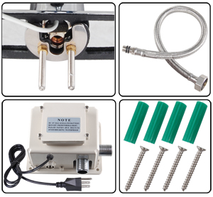
Sensor Faucet Packing List
Installation instruction
|
one copy
|
|
Faucet and sensor assembly (including trim plate with chrome and 800MM fiber optic cable)
|
one piece
|
|
Trim plate 162.5X65mm
|
one piece
|
|
Finger nuts ø 10mm
|
two pieces
|
|
Studs ø 10X45mm
|
two pieces
|
|
Washer gaskets
|
two pieces
|
|
Base gasket
|
one piece
|
|
Solenoid valve module assembly for battery powered model (including solenoid enclosure, solenoid body, and battery compartment).
|
one piece
|
|
Flex hose (Length: 600mm)
|
one piece
|
|
Screws M3X8mm
|
six pieces
|
|
Self-tapping screw M3X17mm
|
four pieces
|
|
Plastic wall anchors ø7X27mm
|
four pieces
|
|
|
|
|
|
Operation:
1. Place hands under spout and directly in front of neck mounted sensor, water will begin to flow out in less than a second,
water flow rate is governed by aerator and supply pressure, water temperature is governed by position of water mixture
selector, as well as water temperature in supply pipes. Please remember, automatic faucets employ
presence not motion sensors. An idle object placed directly underneath spout will immediately activate faucet.
2. Remove hands, water will cease to flow within 1-3 seconds.
3. If hands are left underneath spout for more than 60 seconds, water will automatically shut off. To initiate flow again move hands away from faucet and start at step 1.
4. When attempting to run water over small objects such as tooth brush, it may be necessary to bring object closer to sensor to initiate water flow, when water begins to flow, move object back under stream of water. Once user gets the feel of the faucet this step may be skipped.
5. Faucets with water mixture selector above the sink. Water mixture ratio is adjusted from hot to cold and anywhere in
between by moving lever. Battery Replacement Instructions:
Batteries should provide 12 to 36 months of reliable service mostly depending on the make of battery used and the frequency of
usage among other factors. Battery weakness is indicated by constantly flashing led light within the sensor capsule. When
replacing batteries please follow these simple steps:
1. Unplug Battery from faucet.
2. Unfasten the 4 Philips screws that hold the enclosure cover on, pull enclosure cover off.
3. Replace batteries with 4 AA Alkaline batteries, make sure batteries are placed in their proper position.
4. Re-install battery pack into the Faucet.
5. Test faucet prior to placing enclosure cover back on.
Trouble Shooting:
Faucet does not operate, red light does not blink:
1. Batteries need replacing, replace batteries, see battery replacement instructions.
2. Sensor wire loose, unplugged, plugged improperly, plug sensor wire properly. See installation instructions.
Water flows out of faucet even though hands or objects are not present under spout:
1. Objects (such as sink lip) are present in front of sensor. (See special installation note at the back page).
2. Battery wire not plugged in, batteries need replacing.
Faucet does not operate, red light blinks in response to approaching objects:
1. No water, very low water pressure in supply pipes, supply valves closed.
2. Water pressure very high, well above 115 PSI.
3. Screen filter severely clogged up.
4. Supply hoses severely kinked.
Faucet leaks, drips:
Constant leaks or drips indicate defective solenoid valve, send Faucet Automator for repair or contact an authorized plumbing professional.
Faucet continues to run for 30 -60 seconds after hands are removes:
This very rare condition generally occurs due to over sensitivity on the part of the sensor, system water pressure well above 70psi
and an over lit bathroom environment. This condition is always field curable.
1. Turn down water pressure at both angle stops.
2. Adjust sensor range. See Sensor Range Adjustment in this manual.
3. Objects (such as sink lip) are present in front of sensor. (See special installation note at the back page).
LIMITED WARRANTY LIMITED WARRANTY
Fontana Sensor Faucets warrant this faucet to be free of defects for a period of one
year from date of purchase. Fontana will replace, free of charge, during
this warranty period, parts that prove defective when properly installed and
under normal use and service. Damage that occurs as a result of abuse,
improper installation, environmental conditions, or improper application will
void this warranty. Products must be shipped with postage and handling
prepaid, along with dated proof of purchase. This warranty does not cover
installation or any other labor charges. it does not cover shipping and
handling of both replacement parts and returned defective parts. Products
or components that have been altered or in any way modified will not be
covered under this warranty. Replacement parts are under warranty only for
the remaining period under the initial warranty. Some states do not allow for
exclusion of incidental or consequential damage.
Special Installation Note
Automatic faucets are design to perform properly in a variety of applications. There are some conditions, however, that may adversely
impact the faucets ability to perform. Please note the following conditions prior to installing you new faucet:
1. Your automatic faucet is designed for indoor applications. This faucet is not designed for outdoor applications.
2. Avoid installing your new faucet in direct sunlight. Direct sunlight that is focused on sensor will temporarily disable faucets sensing capabilities.
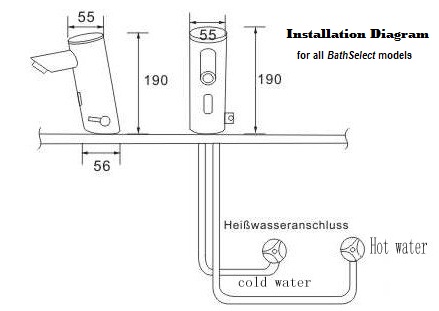
3. When installing your faucet to your counter top please view the drawing below and read accompanying note.
4. When choosing a location to install the Faucet Automator, make sure that it will not be in direct contact of copious amounts of water.
5. If you choose to install your faucet to one water source only, do not install to hot water only as this may result in scalding injury.
6. When installing more than one faucet:
For optimal performance couple spout and Faucet Automator (the gray box) that were shipped together.
See also:
Basic tools needed for Installing Sensor Faucet
Sensor Faucet Frequently Asked Question - FAQ
Commercial Sensor Faucets
ADA Handsfree Touchless Sensor Faucet compliance guide
| 
